In many foundation and retaining systems, failure does not begin with vertical movement. It starts laterally. Soil pressure builds behind retaining walls, basement walls bow inward, waterfront structures creep, and load paths shift in ways shallow reinforcement cannot restrain. Helical tieback anchors exist to address these forces directly, transferring tension loads into stable ground beyond the active failure zone.
In 2026, helical tieback anchors are no longer treated as secondary stabilization elements. Engineers now evaluate them as primary load-resisting components, where installation torque, anchor geometry, corrosion exposure, and bond length determine long-term performance. Their effectiveness depends not just on reaching design loads, but on how reliably those loads are developed and verified in real ground conditions.
This guide explains what helical tieback anchors are, how they work, where they are used, and why modern foundation design increasingly relies on them to control lateral movement and structural risk.
Key Takeaways
Helical tieback anchors control lateral movement by transferring tensile loads beyond the active failure zone, reducing wall and soil deformation risk.
Installation torque, embedment depth, and real-time monitoring provide measurable feedback, ensuring anchor capacity matches design assumptions.
Modern practice treats tiebacks as primary structural elements, with geometry, corrosion protection, and load duration determining long-term performance.
Helical tieback anchors are ideal for retrofit, urban, waterfront, and infrastructure sites where excavation, vibration, or access is limited.
TorcSill provides engineering-led guidance, selecting and installing anchors with monitored data to ensure reliable performance under real site conditions.
What are Helical Tieback Anchors? Everything You Need to Know
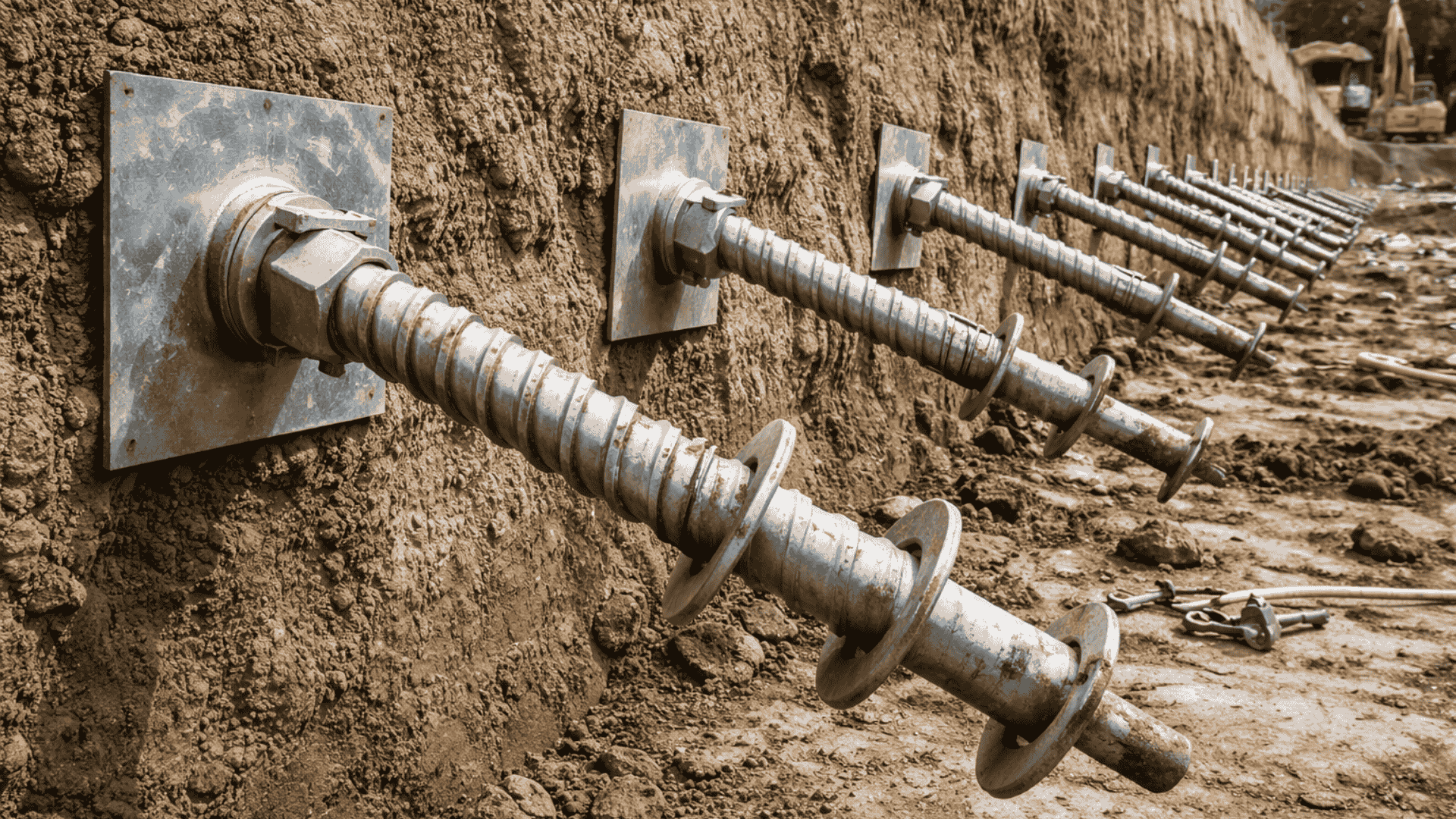
Helical tieback anchors are deep foundation anchoring systems designed to resist lateral forces by transferring tensile loads from a structure into stable soil or rock beyond the active failure zone. They are most commonly used to stabilize retaining walls, basement walls, seawalls, bulkheads, and earth-retaining structures where lateral earth pressures or surcharge loads must be restrained.
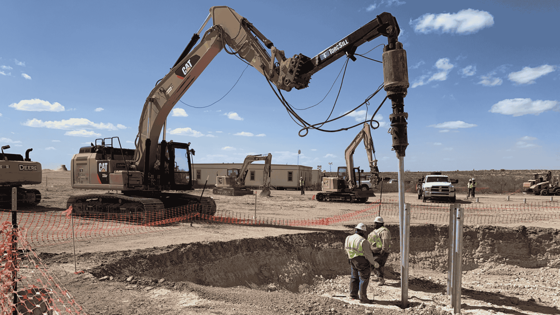
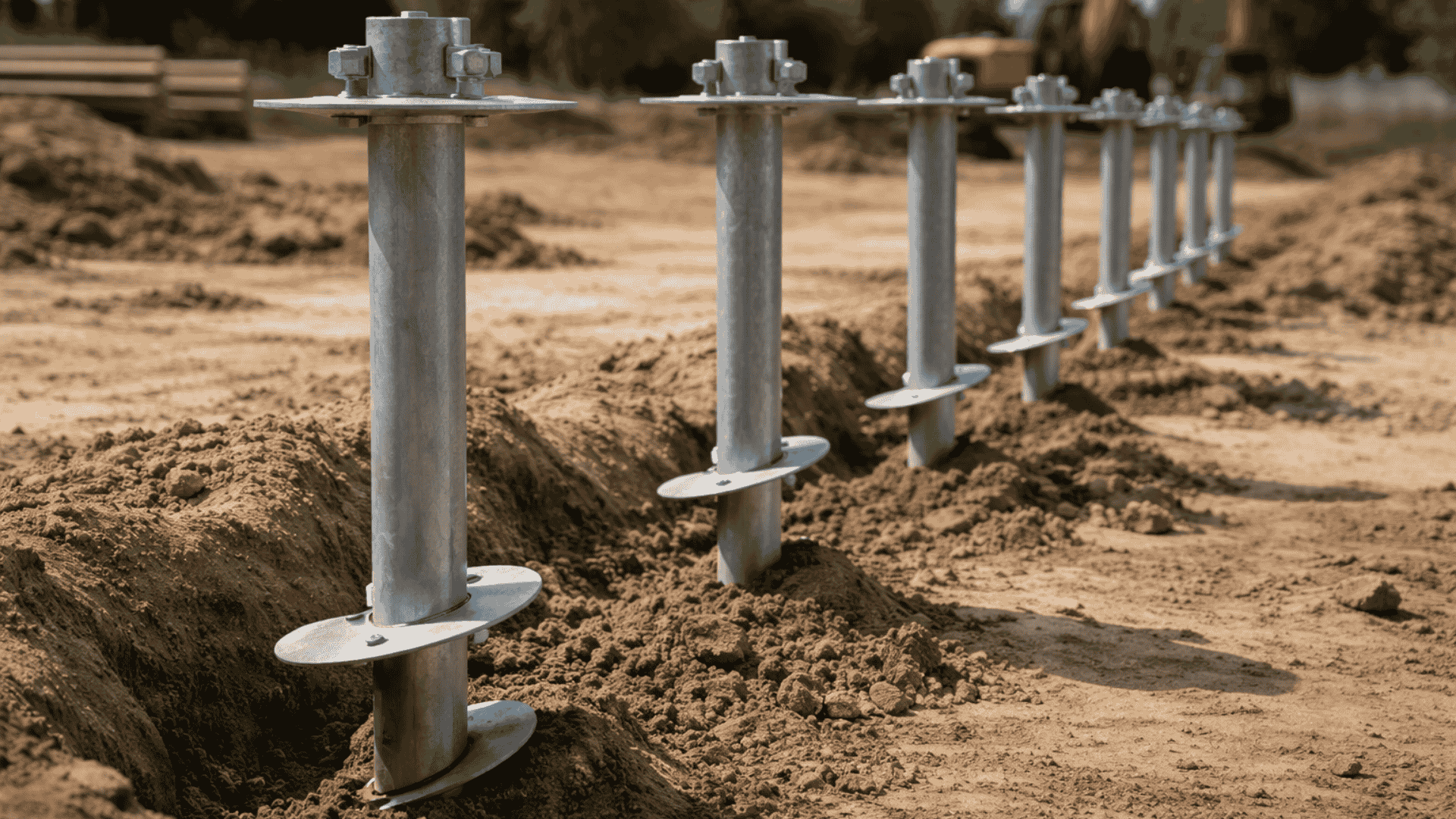
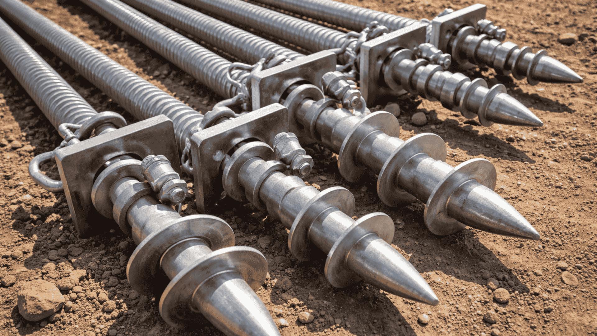
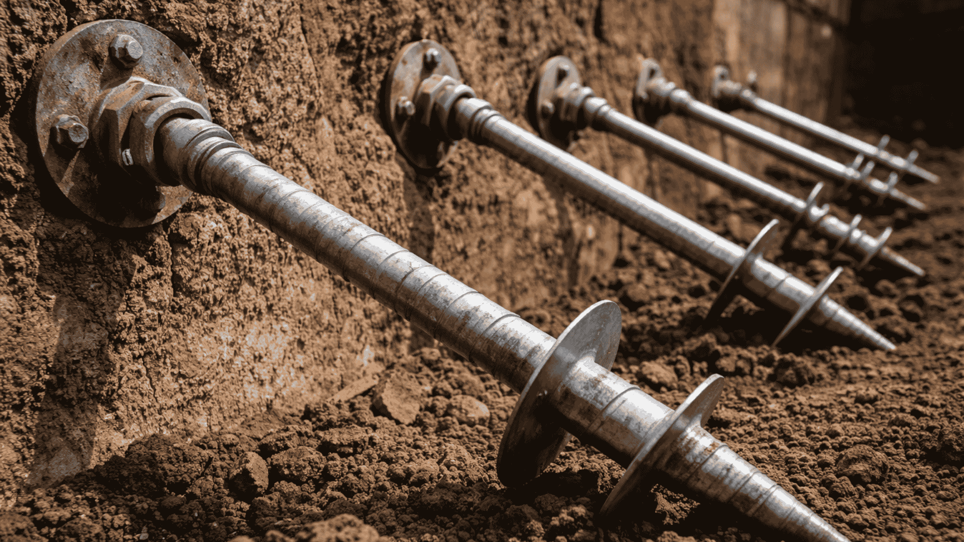
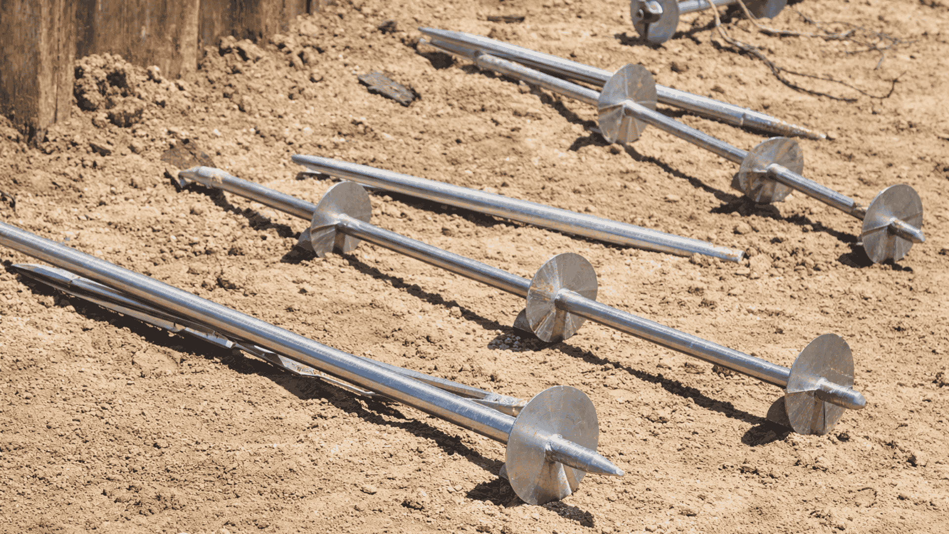
A helical tieback anchor consists of a steel shaft fitted with one or more helical bearing plates. During installation, the anchor is advanced into the ground through controlled rotational torque rather than impact or excavation. The helices engage competent soil strata, allowing the anchor to develop tensile resistance through bearing and friction mechanisms.
Unlike surface-mounted restraints or gravity-based systems, helical tieback anchors work by extending the load path away from the structure. This allows lateral forces to be resisted at depth, reducing wall movement and controlling long-term deformation under sustained soil pressure.
Key characteristics of helical tieback anchors include:
Tension-based load transfer: Anchors resist pull-out forces by mobilizing bearing capacity at the helices, providing reliable resistance to lateral earth pressures.
Predictable installation feedback: Installation torque offers a measurable indicator of anchor capacity, improving confidence in field performance.
Minimal ground disturbance: Rotational installation limits vibration and soil displacement, making tiebacks suitable near existing or sensitive structures.
Adaptability to site constraints: Anchors can be installed at various inclinations and lengths to bypass obstructions and reach competent bearing zones.
Immediate load application: Once installed, anchors can be proof-tested and loaded without waiting for curing or soil reconsolidation.
Understanding how these anchors interact with soil under sustained tension is essential for designing retaining systems that remain stable over the full service life of the structure.
Consult with a TorcSill engineer to assess anchor configuration, installation data, and soil interaction to support reliable helical tieback anchor performance.
How Helical Tieback Anchors Work in Practice
Helical tieback anchors are installed to transfer lateral earth pressures from retaining structures into stable ground beyond the active failure zone.
Each stage of installation is engineered to control load paths, verify tensile capacity, and limit long-term wall movement under service conditions.
Pre-Installation Planning and Engineering
Before installation begins, engineers define the tieback anchor system based on lateral load demands, wall geometry, and subsurface conditions. This stage includes:
Reviewing geotechnical data to identify soil stratigraphy, shear strength, groundwater conditions, and the expected failure wedge behind the structure.
Determining anchor inclination, spacing, embedment length, and helix configuration to ensure anchors extend into competent passive soil.
Establishing performance criteria such as target installation torque, minimum embedment depth, and allowable anchor displacement.
Identifying constraints including nearby utilities, property lines, existing foundations, or access limitations.
Careful upfront engineering ensures anchors engage the correct soil zone and develop predictable tensile resistance under load.
Site Preparation and Layout
Accurate positioning is critical for effective load transfer and constructability. Key activities include:
Surveying and marking anchor locations and installation angles on the retaining structure.
Preparing working platforms and access for installation equipment.
Verifying clearances for anchor inclination to avoid conflicts with buried or adjacent structures.
Errors in layout or angle can reduce anchor effectiveness by placing helices within the active failure zone.
Equipment Mobilization and Calibration
Installation equipment is selected based on anchor size, soil resistance, and access conditions. This typically includes:
Hydraulic drive heads capable of delivering controlled rotational torque.
Excavators or compact rigs configured for angled installation.
Instrumentation for real-time torque, depth, and rotation monitoring.
Equipment calibration ensures installation torque readings are accurate, as these values are used to estimate anchor tensile capacity.
Anchor Positioning and Alignment
Each anchor is positioned at the specified inclination and aligned before rotation begins:
Confirming installation angle and orientation using guides or inclinometer tools.
Ensuring the anchor shaft is properly engaged with the drive head to avoid eccentric loading.
Verifying alignment relative to wall plates or wale systems to maintain a direct load path.
Correct alignment reduces bending stresses and ensures uniform load transfer from the structure to the anchor.
Advancing the Anchor and Monitoring Installation
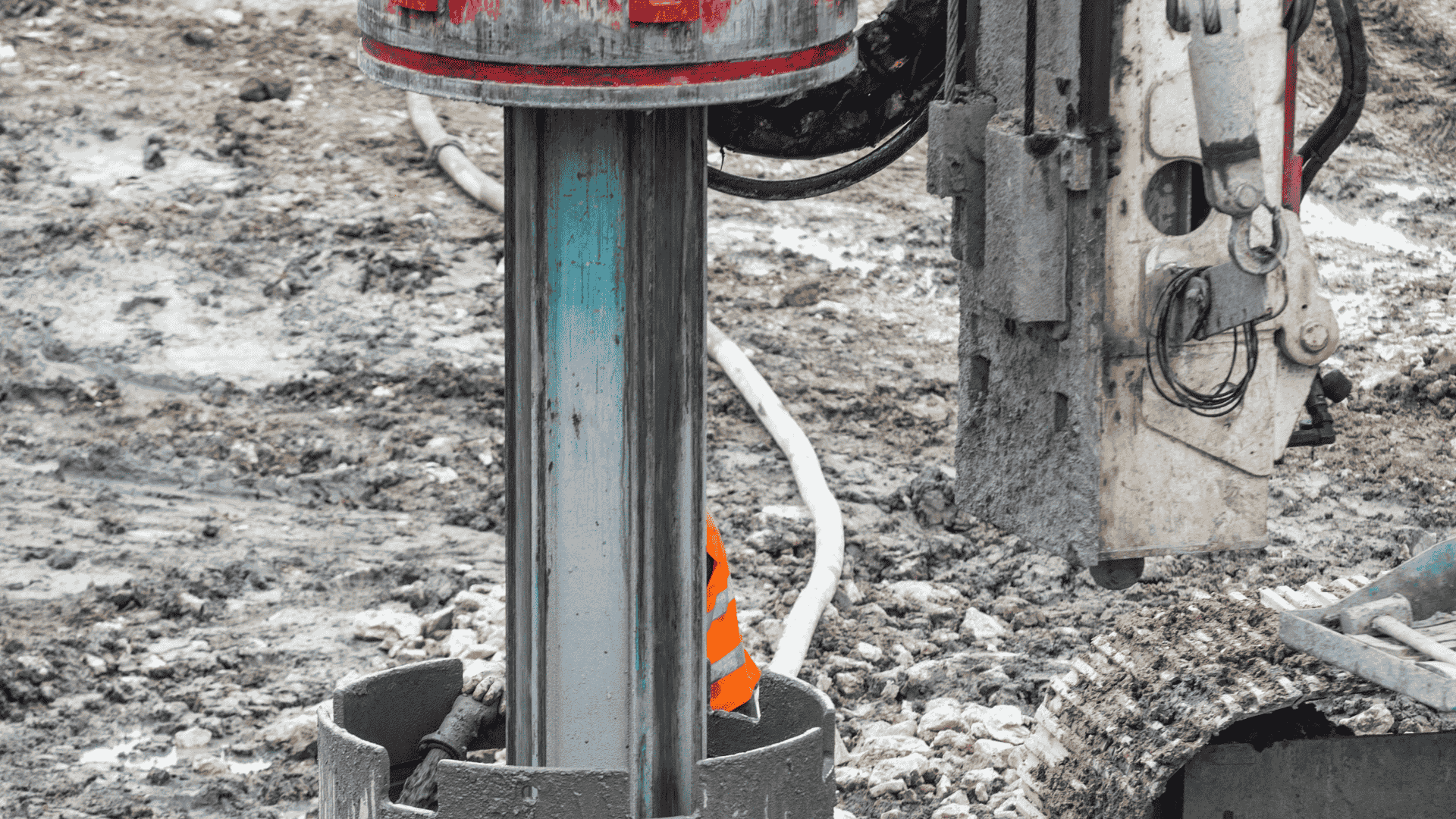
The helical anchor is advanced into the ground through controlled rotational installation:
Torque is applied gradually to advance helices without disturbing surrounding soil excessively.
Installation torque and depth are recorded continuously to identify soil transitions and resistance trends.
Sudden changes in torque may indicate obstructions, weak layers, or entry into competent bearing strata.
This real-time data provides direct insight into subsurface behavior and anchor engagement.
Achieving Design Embedment and Capacity Criteria
Installation continues until predefined acceptance criteria are met, which may include:
Reaching a minimum embedment length beyond the failure wedge.
Achieving target installation torque correlated with required tensile capacity.
Confirming consistent resistance indicative of competent soil engagement.
If criteria are not achieved, engineers may adjust anchor length, helix configuration, or installation location before proceeding.
Load Testing and Verification
Once installed, anchors are typically verified through proof or performance testing:
Controlled tensile loads are applied incrementally to confirm capacity and displacement limits.
Load–displacement behavior is monitored to assess stiffness, creep response, and anchor performance.
Test results are reviewed to confirm anchors meet service and ultimate limit state requirements.
Testing validates that installation data accurately reflects in-ground anchor behavior.
Structural Connection and Load Transfer
After verification, anchors are integrated into the retaining system:
Installing wall plates, wales, or brackets to connect anchors to the structure.
Applying specified lock-off loads where required to control initial wall movement.
Confirming alignment of tensile load paths from the wall into the anchor shaft.
Proper connection ensures lateral earth pressures are transferred efficiently into stable ground.
Helical tieback anchor installation is not a single operation, but a sequence of engineered decisions that convert lateral soil pressures into controlled tensile resistance. When planned, monitored, and verified correctly, tieback anchors provide predictable wall stability and long-term performance under variable ground conditions.
When soil conditions, wall loads, and anchor requirements vary, engineered solutions help reduce uncertainty. TorcSill’s helical tieback systems are designed to deliver predictable tensile capacity across challenging ground conditions. Early engineering involvement supports clearer design decisions and reliable wall performance.
Where Helical Tieback Anchors are Used in 2026
Helical tieback anchors are used where retaining structures must resist lateral earth pressures and where conventional gravity or cantilever solutions are not practical. Their ability to develop tensile resistance in stable soil zones makes them especially effective in constrained, variable, or retrofit environments.
Common applications include:
1. Retaining walls and earth retention systems: Helical tiebacks are widely used to stabilise permanent and temporary retaining walls by transferring lateral loads into competent soil beyond the active failure wedge. They help control wall movement and reduce structural demands on wall sections.
2. Basement and below-grade structures: In deep basements or below-grade construction, tieback anchors are used to support excavation support systems and permanent walls where space constraints prevent the use of internal bracing or thicker wall sections.
3. Slope stabilisation and landslide mitigation: Tieback anchors provide stabilizing tensile forces to restrain soil movement on slopes or embankments. They are often used where access is limited and where traditional ground improvement methods are impractical.
4. Waterfront and marine retaining structures: Seawalls, bulkheads, and quay walls use helical tieback anchors to resist lateral loads from soil, water pressure, and surcharge loads. Their installation with minimal vibration is beneficial near existing marine infrastructure.
5. Infrastructure and transportation projects: Helical tiebacks are applied in highway widening, bridge abutments, and rail corridors where excavation support is required without disrupting adjacent assets or right-of-way boundaries.
6. Retrofit and remediation projects: For failing or deflecting retaining structures, helical tieback anchors allow stabilisation without full demolition. Anchors can be installed through existing walls to restore capacity and limit further movement.
Across these applications, the effectiveness of helical tieback anchors depends on correct anchor layout, embedment beyond the failure zone, and verification of tensile capacity. Understanding site-specific soil behavior and installation response is critical to ensuring anchors deliver long-term lateral stability under service conditions.
Why Modern Foundation Prefers Helical Tieback Anchors
Modern foundation design places greater emphasis on predictability, constructability, and performance verification under real site constraints. Helical tieback anchors align well with these priorities, which is why their use has expanded significantly in recent years.
They provide measurable, verifiable performance
Installation torque offers a direct, real-time indicator of anchor capacity. This allows engineers to confirm tensile resistance during installation rather than relying solely on theoretical soil parameters, reducing uncertainty in lateral load design.
They minimise site disruption and construction risk
Helical tiebacks are installed without large excavations, grouting operations, or heavy vibration. This makes them well suited to urban, occupied, or environmentally sensitive sites where ground movement and noise must be controlled.
They perform reliably in variable ground conditions
By advancing anchors to depth until target torque or embedment is achieved, designers can account for subsurface variability more effectively than with fixed-length systems. This adaptability improves consistency across a site with changing soil profiles.
They support efficient structural design
Tieback anchors reduce bending and section demands on retaining walls, allowing slimmer wall sections or simpler temporary works. This often results in material savings and faster construction schedules without compromizing safety.
They integrate well with modern verification-driven design
Current practice treats installation data as part of the design validation process. Helical tieback anchors generate continuous, interpretable data that supports engineering review, acceptance decisions, and long-term confidence in performance.
As foundation design shifts toward data-backed decisions and controlled construction outcomes, helical tieback anchors offer a combination of measurable capacity, installation flexibility, and low-impact construction that aligns with modern engineering expectations.
How TorcSill Optimizes Helical Tieback Anchor Installation
Helical tieback anchors are often used where lateral loads, ground variability, and construction constraints intersect. Their performance depends not only on theoretical capacity, but on how installation behaviour confirms load transfer under real site conditions.
TorcSill supports helical tieback anchor decisions by integrating engineering review with installation-stage data, ensuring anchors perform as intended from design through construction.
Key ways TorcSill adds value for helical tieback anchor projects include:
Engineering-led anchor system selection: TorcSill evaluates soil conditions, load demand, anchor geometry, and load orientation to select helical tieback anchor systems that align with project-specific structural and geotechnical requirements.
Controlled installation with real-time capacity verification: Anchors are installed by TorcSill using monitored torque and embedment data, allowing installation resistance to be directly correlated with design capacity rather than assumed from theoretical models alone.
Interpretation of installation behaviour in variable ground: Torque trends, advancement rates, and refusal behaviour are reviewed during installation to identify changes in soil response that may influence anchor performance or long-term creep behaviour.
Installation-driven design refinement when conditions vary: When subsurface conditions differ from expectations, TorcSill supports informed adjustments to anchor length, helix configuration, or spacing to maintain required load capacity without overdesign.
Verification, documentation, and load-transfer confidence: Installation records are documented and reviewed to confirm that anchors meet acceptance criteria and integrate correctly with structural elements, supporting reliable load transfer and long-term stability.
By integrating engineering judgement directly into installation, TorcSill ensures helical tieback anchors deliver predictable performance, reduced uncertainty, and risk-aware foundation outcomes.
Conclusion
Helical tieback anchors play a critical role in resisting lateral and uplift forces where soil variability, space constraints, and structural sensitivity limit conventional anchoring solutions. Their effectiveness depends not only on anchor geometry, but on how installation torque, embedment behaviour, and load transfer mechanisms align with design assumptions.
Early engineering oversight during anchor selection and installation helps confirm capacity, manage subsurface uncertainty, and avoid performance gaps under service loads. Interpreting field behaviour as installation progresses reduces risk and supports predictable, long-term anchor performance.
Consult a TorcSill engineer to ensure helical tieback anchor selection and installation data are correctly interpreted for foundation and earth-retention design.
Frequently Asked Questions (FAQs)
How is long-term load performance verified for helical tieback anchors?
Long-term performance is confirmed by reviewing installation torque, embedment depth, and soil resistance trends. Engineers also evaluate creep, sustained loads, and anchor stiffness to ensure the system maintains capacity over decades.
Can helical tieback anchors allow for future load increases?
Yes. Anchors can be specified with additional reserve capacity, extra helices, or longer shafts. This allows future structural modifications or added surcharge loads without compromizing stability.
How does groundwater affect helical tieback anchor behaviour?
Groundwater impacts soil strength, effective stress, and corrosion potential. Proper design accounts for water table fluctuations, drainage, and protective coatings to maintain long-term tensile resistance.
What does inconsistent installation torque across anchors indicate?
Variations in torque usually signal changes in soil layers, obstructions, or compaction differences. Engineers may adjust anchor length, spacing, or helix size to ensure uniform load transfer and reliability.
Are helical tieback anchors suitable for permanent structures?
Yes, when corrosion protection, load duration, and soil-structure interaction are engineered for the intended service life. Correct installation and monitoring ensure anchors remain stable under long-term lateral loads.