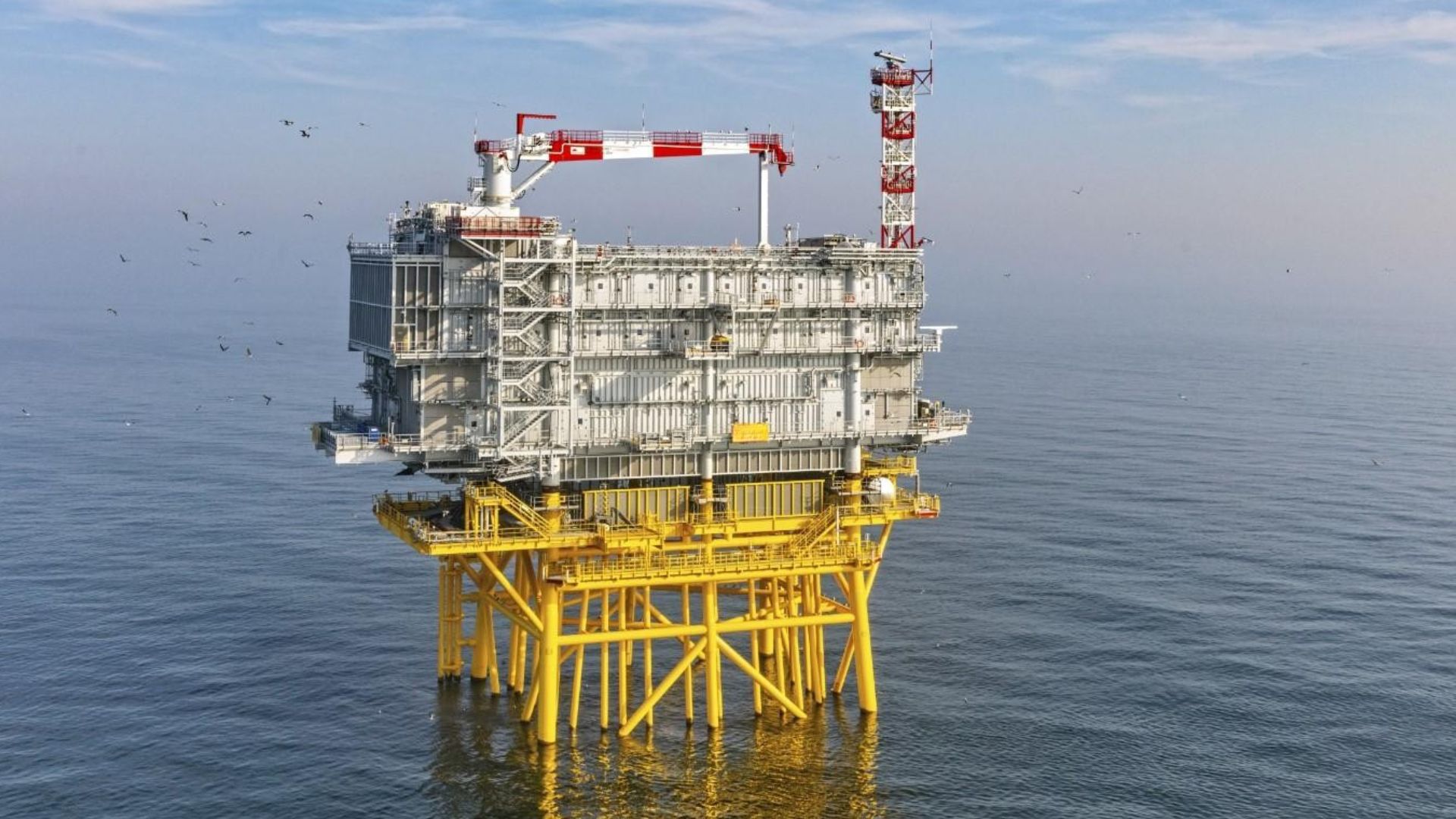
Offshore substations are a critical link between offshore energy generation and onshore transmission networks, particularly in the rapidly expanding U.S. offshore wind sector. While commercial-scale offshore wind is still in its early deployment phase in the United States, activity is increasing with projections of significant capacity additions through the late 2020s.
The offshore wind capacity is projected to reach a total of nearly 6 GW by 2029 under current forecasts. At the core of many offshore substation foundations is the jacket structure, a multi-legged, braced steel framework designed to safely transfer complex loads from the topside structure into the seabed.
The importance of jacket design and installation has grown alongside increasing offshore wind capacity along the U.S. East Coast, Gulf of Mexico, and emerging Pacific projects.
This guide provides a technical overview of offshore substation jacket design and installation, covering foundation selection, piling systems, offshore installation procedures, safety management, and regulatory compliance.
Key Takeaways:
Offshore substation jackets provide stable, long-life foundations, transferring extreme structural and environmental loads safely into diverse seabed conditions.
Jacket design integrates geotechnical data, metocean loading, fatigue performance, corrosion protection, and constructability to ensure reliability and regulatory compliance.
Piling system selection, driven, drilled, or specialized, depends on soil conditions, environmental constraints, and offshore installation feasibility.
Precise fabrication, installation sequencing, alignment control, and grouting quality are critical to avoiding delays, rework, and long-term performance risks.
Turnkey, foundation-led execution reduces interface risk, improves safety, and delivers predictable offshore substation jacket performance across the full asset lifecycle.
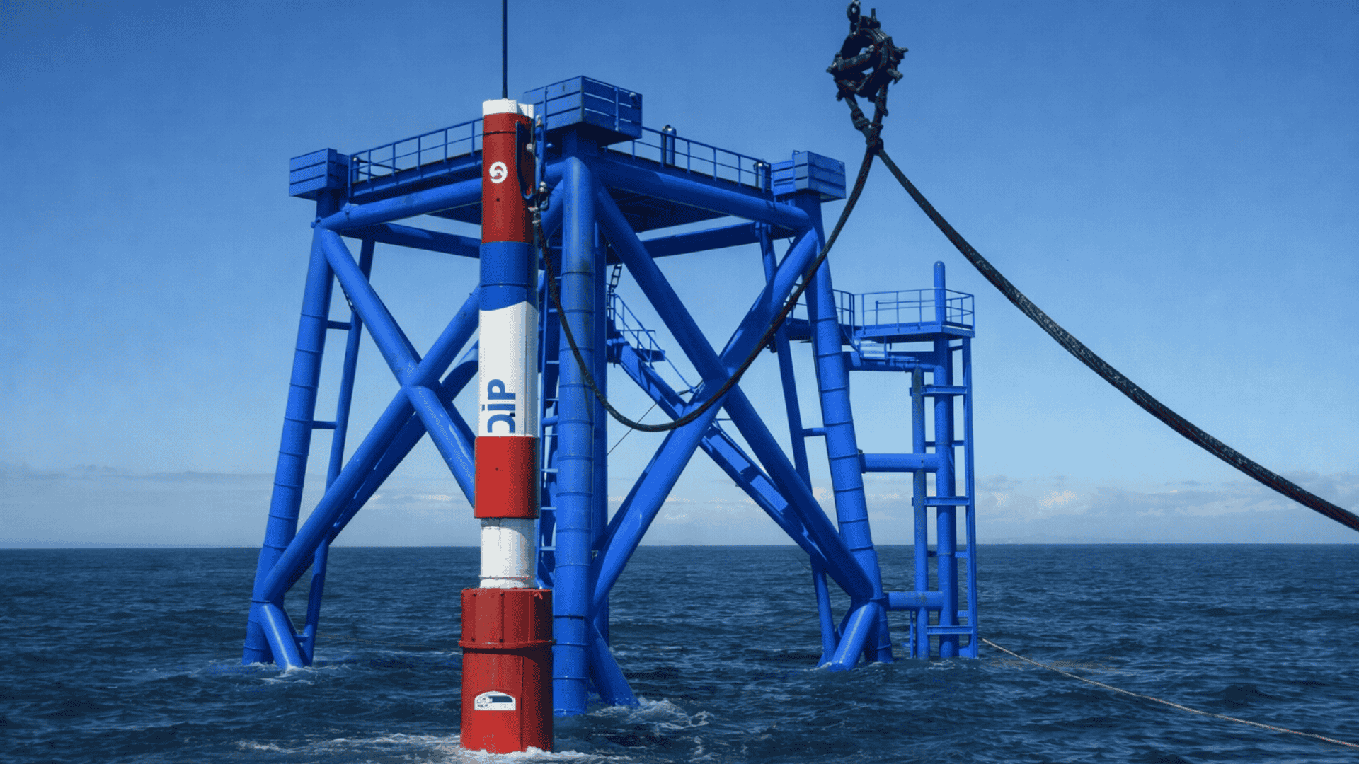
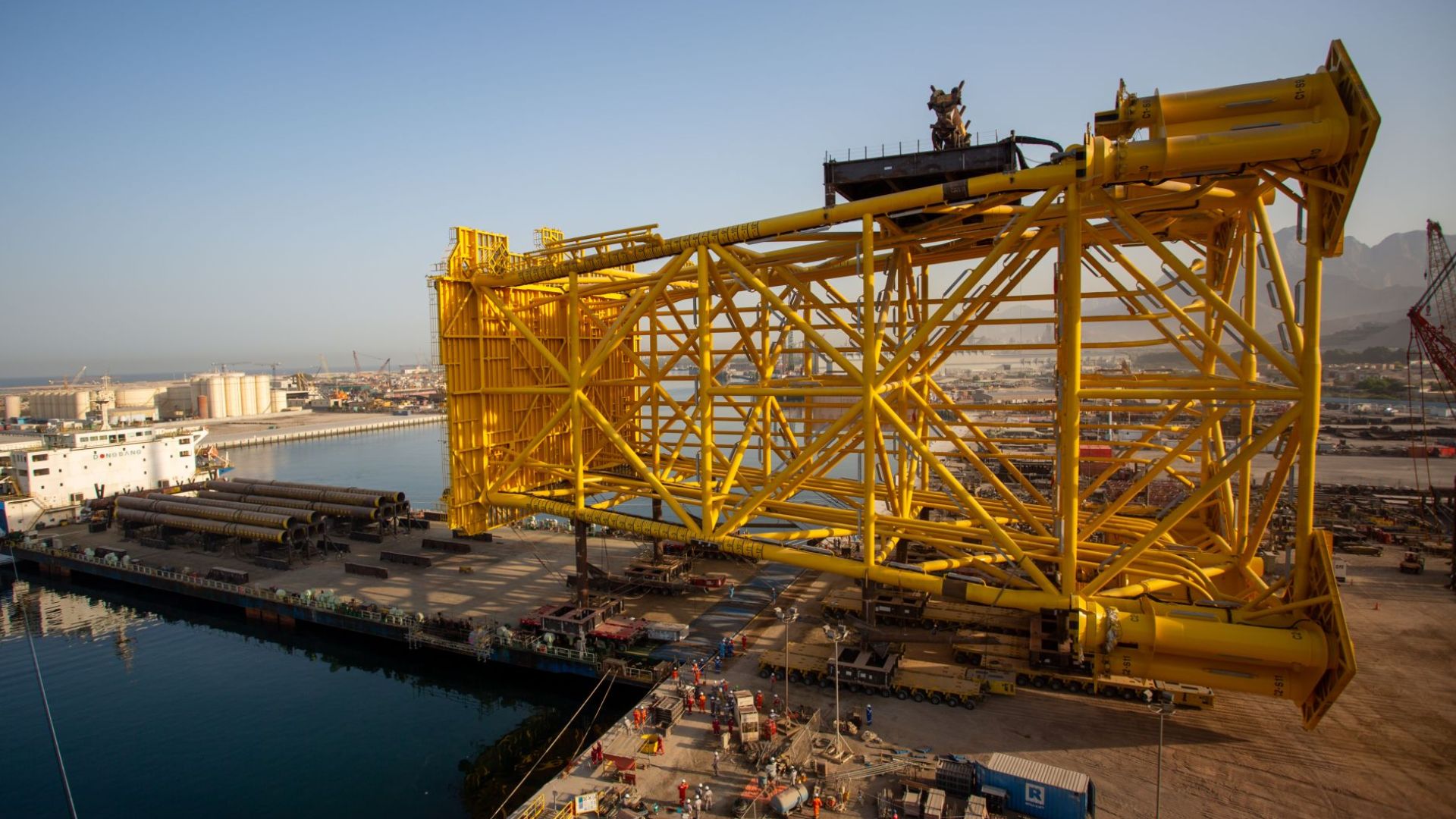
What Is an Offshore Substation Jacket?
An offshore substation jacket is a steel, space-frame foundation structure designed to support offshore electrical substations and related energy infrastructure. It transfers vertical, lateral, and overturning loads from the substation topside into the seabed through piles or other foundation systems.
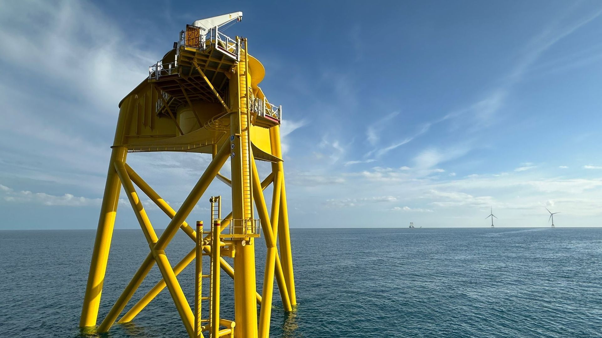
Jackets are widely used in offshore environments where water depth, soil conditions, and environmental loading exceed the practical limits of monopile foundations.
Jacket structures are engineered to provide high structural redundancy, stiffness, and fatigue resistance, making them well-suited for long-life offshore substations that must remain operational under continuous environmental loading.
Purpose of Jacket Foundations in Offshore Substations
The primary functions of an offshore substation jacket include:
Supporting the weight of the electrical topside, including transformers, switchgear, and auxiliary systems
Resisting lateral loads from wind, waves, and currents
Managing overturning moments generated by tall, heavy topside structures
Providing long-term fatigue performance under cyclic loading
Ensuring stable load transfer to the seabed across variable soil profiles
Because offshore substations act as central nodes in energy transmission networks, jacket foundations are designed with conservative safety factors and robust detailing to minimize maintenance and operational risk over the asset’s service life.
Engineering and Structural Design of Jacket Foundations
The engineering and structural design of offshore substation jacket foundations must balance strength, stiffness, fatigue resistance, constructability, and long-term durability.
For U.S. offshore projects, design approaches must align with site-specific environmental data, geotechnical conditions, and applicable offshore codes, while remaining practical for fabrication and offshore installation.
Design Load Cases
Offshore substation jackets are designed to withstand a range of operational, environmental, and accidental load cases, including:
Operational loads: Dead loads from the jacket and topside, equipment loads, and live loads during maintenance
Environmental loads: Wind, wave, current, and ice (where applicable)
Extreme event loads: Hurricanes, storm surge, and seismic events
Accidental loads: Vessel impact, dropped objects, and abnormal operating conditions
Load combinations are assessed to ensure structural integrity, serviceability, and fatigue performance throughout the design life of the asset.
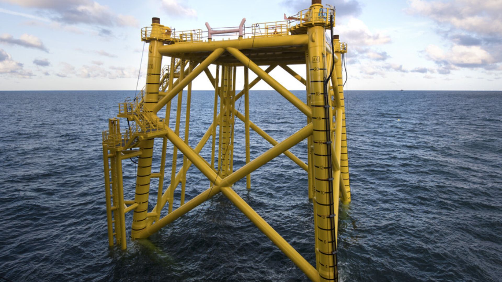
Jacket Geometry and Member Sizing
Jacket geometry is driven by water depth, topside footprint, pile layout, and installation constraints. Engineers optimize:
Leg spacing and inclination for stability and load distribution
Bracing configuration to control deflections and dynamic response
Member diameters and wall thicknesses to meet strength and fatigue requirements
Structural analysis typically includes global structural modeling and local joint checks, ensuring compliance with allowable stress, ultimate limit state, and fatigue criteria.
Material Selection and Corrosion Protection Systems
Structural steel selection considers strength, weldability, fracture toughness, and fatigue performance. Common practices include:
Use of offshore-grade structural steels
Corrosion allowance integrated into member thickness
Multi-layer protective coating systems
Cathodic protection using sacrificial anodes or impressed current systems
These measures are essential for achieving a 25–30+ year design life in aggressive marine environments.
Pile-to-Jacket Connection Systems
The interface between piles and jacket legs is a critical design element that directly affects load transfer and constructability.
Common connection systems include:
Grouted connections: Provide uniform load transfer and high axial capacity
Bolted connections: Allow for faster installation and reduced offshore grouting operations
Connection selection depends on pile type, installation tolerances, environmental conditions, and inspection requirements. Proper detailing is essential to control fatigue stresses and ensure long-term performance.
By integrating structural analysis, geotechnical design, and offshore constructability, engineered jacket foundations can be optimized for both performance and installation efficiency.
Piling and Foundation Systems for Jacket Structures
Jacket foundations typically rely on multiple piles installed through or adjacent to jacket legs, providing redundancy, high load capacity, and adaptability to variable soil conditions.
1. Driven Steel Piles
Driven steel piles are the most common foundation solution for offshore substation jackets due to their proven performance and high axial and lateral capacity.
Key characteristics include:
Large-diameter steel tubular piles
Penetration depths designed to achieve the required axial, lateral, and uplift capacity
Installation through jacket leg sleeves or guides
Controlled alignment to meet tight installation tolerances
Driven piles are well-suited for sandy and cohesive soils commonly encountered along the U.S. East Coast and Gulf of Mexico. However, pile drivability analyzes are critical to manage refusal risks and ensure pile integrity during installation.
Installation Tolerances and Alignment Control
Accurate pile positioning is essential for effective pile-to-jacket connections. Typical controls include:
Pre-installed pile guides within jacket legs
Real-time monitoring of pile inclination and penetration
Survey verification before grouting or final connection
Maintaining tight tolerances reduces stress concentrations and ensures proper load transfer.
2. Drilled and Grouted Piles
Drilled and grouted piles are used where seabed conditions limit driven pile installation, such as:
Hard strata or weak rock formations
Highly layered or variable soil profiles
Noise-sensitive marine environments
These systems involve drilling to design depth, installing a steel pile or casing, and grouting the annulus to achieve structural and geotechnical capacity. While typically slower to install, drilled piles offer greater control in challenging ground conditions.
Advantages in Sensitive Marine Zones
Drilled and grouted piles generate lower noise and vibration levels compared to impact driving, making them suitable for projects with strict environmental restrictions or marine mammal protection requirements.
3. Helical Piles and Anchors (Specialized Applications)
While not commonly used as primary foundations for offshore substation jackets, helical piles and anchors serve specialized roles, including:
Temporary works and construction staging platforms
Access systems and auxiliary supports
Mooring or anchoring of temporary offshore equipment
Helical systems offer precise installation, immediate load capacity, and minimal seabed disturbance, making them valuable in specific offshore construction scenarios. TorcSill’s experience with engineered helical solutions allows these systems to be deployed efficiently where appropriate.
Offshore Jacket Installation Procedure
The offshore installation of a substation jacket is a highly coordinated marine operation requiring precise execution, real-time monitoring, and strict safety controls. Each step, from seabed preparation to final connection verification, directly affects structural performance and long-term reliability.
For U.S. offshore projects, installation procedures must also align with regulatory requirements, weather windows, and environmental protection measures.
Seabed Preparation and Positioning
Prior to jacket installation, the seabed is prepared to ensure stable support and accurate placement. Typical activities include:
Verification of seabed levels and obstructions
Local dredging or leveling if required
Installation of temporary seabed markers or positioning aids
Accurate positioning systems, including GPS and acoustic references, are used to confirm jacket location relative to design coordinates.
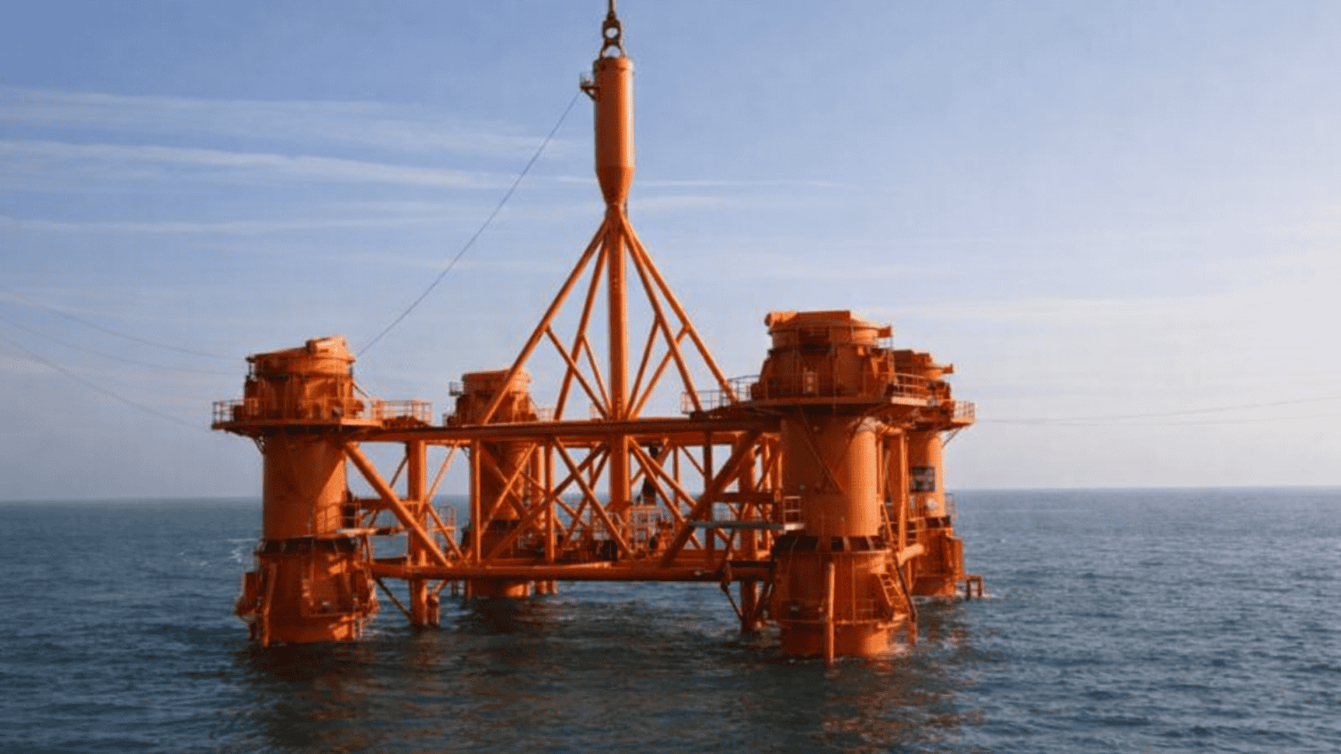
Jacket Lifting, Lowering, and Orientation
The jacket is lifted from the transport vessel using a heavy-lift crane and carefully lowered to the seabed. Critical considerations include:
Controlled lifting to limit dynamic loads
Monitoring of jacket orientation during lowering
Alignment of jacket legs with planned pile locations
Installation tolerances are continuously checked to ensure compatibility with subsequent piling and grouting operations.
Pile Installation Through Jacket Legs
Once the jacket is positioned, piles are installed through pre-installed sleeves or guides within each jacket leg. This process involves:
Driving or drilling piles to design penetration depths
Monitoring pile inclination, penetration rate, and resistance
Verifying pile position prior to final connection
Pile installation is sequenced to maintain jacket stability and prevent uneven load distribution.
Grouting and Connection Verification
After pile installation, the annular space between the pile and jacket leg is filled with structural grout to create a rigid load-transfer connection. Key steps include:
Cleaning and preparation of the annulus
Controlled grout mixing and placement
Monitoring grout flow, pressure, and volume
Verification of grout strength and integrity
Proper grouting is essential to ensure axial and lateral load transfer from the jacket to the foundation piles.
Tolerance Checks and As-Built Documentation
Following installation, comprehensive surveys are conducted to confirm:
Jacket verticality and alignment
Pile positions and penetration depths
Connection completion and grout quality
As-built documentation is compiled to demonstrate compliance with design requirements and regulatory standards.
Safety Management for Jacket Installation
Safety management is a core requirement in offshore substation jacket installation due to the combination of heavy lifting, marine operations, working at height, and variable environmental conditions. A structured, proactive safety approach protects personnel, equipment, and the asset while minimizing downtime and incident risk.
For U.S. offshore projects, safety programs must comply with federal regulations and align with offshore industry best practices.
Offshore Lifting and Marine Operations Safety
Jacket installation involves complex lifting operations that require detailed planning and execution. Key safety measures include:
Verified lifting plans and rigging designs
Crane capacity and stability checks
Clear communication protocols between vessels and crews
Defined lift exclusion zones
Weather and sea-state limits are strictly enforced to prevent unsafe lifting conditions.
Working-at-Height and Confined Space Risks
Installation activities often require personnel to work at height within jacket structures or inside pile sleeves and confined spaces. Risk controls include:
Fall protection systems and access planning
Confined space entry procedures and monitoring
Specialized training for offshore work environments
These measures reduce exposure to high-risk activities during installation.
Vessel Coordination and Exclusion Zones
Multiple vessels may operate simultaneously during jacket installation. Effective vessel coordination includes:
Defined marine traffic management plans
Clear exclusion zones around active operations
Continuous communication between marine supervisors
Proper coordination minimizes collision risks and improves operational efficiency.
Emergency Response and Weather Contingency Planning
Emergency preparedness is essential in offshore environments. Safety planning addresses:
Emergency evacuation and medical response procedures
Equipment recovery and incident response
Weather forecasting and operational standby protocols
Well-defined contingency plans enable rapid response to changing conditions and unforeseen events.
Common Challenges in Jacket Installation Projects
Offshore substation jacket installations are complex, high-risk operations where technical, environmental, and logistical challenges can affect safety, schedule, and cost. Understanding these challenges early allows project teams to develop mitigation strategies and improve overall execution certainty.
Misalignment or Pile Refusal
Pile misalignment or premature refusal can occur due to unexpected soil conditions, obstructions, or installation tolerances being exceeded. These issues may lead to:
Difficulty achieving proper pile-to-jacket connections
Increased stress concentrations at connection points
Installation delays and potential redesign
Early geotechnical investigation and real-time monitoring help reduce these risks.
Weather and Sea-State Delays
Offshore installation activities are highly sensitive to weather conditions. Adverse sea states can:
Halt lifting and piling operations
Extend vessel standby time
Disrupt planned installation sequences
Accurate forecasting and flexible installation windows are essential for managing weather-related delays.
Grouting Quality Issues
Poor grout placement or curing can compromise pile-to-jacket connections. Common causes include:
Inadequate annulus cleaning
Incorrect grout mix or placement procedures
Environmental conditions affecting grout curing
Strict quality control and experienced offshore grouting teams are critical to avoiding rework.
Corrosion and Long-Term Durability Risks
Inadequate corrosion protection can reduce jacket service life and increase maintenance requirements. Risks include:
Coating damage during transport or installation
Insufficient cathodic protection coverage
Accelerated corrosion in splash zones
Durability-focused design and inspection reduce long-term performance issues.
Schedule and Cost Overruns
Interface misalignment between engineering, fabrication, and installation can lead to schedule slippage and cost escalation. Common contributors include:
Late design changes
Inadequate installation planning
Vessel availability constraints
Integrated, turnkey execution helps minimize these risks by aligning all project phases.
TorcSill: Engineered Foundation Solutions for Offshore and Energy Infrastructure
TorcSill is a turnkey foundation engineering, manufacturing, and installation company supporting critical energy, marine, and industrial infrastructure across the United States. With a foundation-led execution model, TorcSill integrates engineering design, custom manufacturing, and field installation to reduce interface risk and improve constructability, an approach well-suited for complex offshore substation jacket projects.
Core capabilities relevant to offshore substation jacket projects include:
Offshore and marine piling solutions
Precision installation and alignment control
Grouted foundation and connection systems
Turnkey delivery from engineering through installation
By aligning engineering intent with offshore execution realities, TorcSill helps offshore energy developers and EPC contractors achieve durable, compliant, and constructible foundation solutions.
Conclusion
Offshore substation jackets are a cornerstone of reliable offshore energy infrastructure, particularly as U.S. offshore wind and transmission projects continue to scale in size and complexity. A robust jacket foundation, designed with site-specific data and installed with precision, ensures structural stability, operational safety, and long-term performance under demanding marine conditions.
Successful projects depend on integrated engineering, disciplined installation procedures, rigorous quality verification, and proactive safety and environmental management. From early geotechnical studies to final as-built documentation, each phase plays a critical role in reducing lifecycle risk and protecting high-value offshore assets.
Planning an Offshore Substation Jacket Installation?
TorcSill supports offshore energy projects with engineered jacket and piling solutions tailored to site-specific conditions and regulatory requirements.
By integrating engineering, piling, and marine construction under one delivery model, TorcSill helps reduce risk and improve performance across the full lifecycle of offshore substation jacket foundations.
Book a call with our engineers today.
FAQs:
1. When should jacket foundation decisions be locked in during an offshore substation project?
Jacket foundation concepts should be finalized before topside FEED completion, as jacket geometry, pile layout, and connection detailing directly influence topside interface loads, lift planning, and installation sequencing. Late foundation changes often trigger cascading redesigns and offshore schedule risk.
2. How do offshore substations differ from turbine foundations in terms of jacket demand?
Offshore substations impose higher sustained vertical loads, larger overturning moments, and stricter serviceability limits than wind turbines. As a result, substation jackets are typically heavier, stiffer, and governed more by fatigue and deflection criteria than by ultimate strength alone.
3. What installation activities typically drive offshore substation jacket critical paths?
Critical paths are often driven by weather-restricted heavy lifts, pile installation rates, and grouting cure times, rather than fabrication alone. Vessel availability and weather downtime usually have a greater schedule impact than steel tonnage.
4. How does jacket foundation design influence future maintenance access?
Leg spacing, bracing layout, and splash-zone detailing can significantly affect boat landing access, inspection reach, and corrosion monitoring. Jackets designed with lifecycle access in mind reduce long-term O&M costs and inspection complexity.
5. Are offshore substation jackets designed differently for AC vs. HVDC substations?
Yes. HVDC substations generally require heavier topsides, larger footprints, and tighter vibration control, which can drive wider leg spacing, increased pile capacity, and stiffer jacket geometries compared to AC substations.