Industry adoption of helical piles continues to grow rapidly as sustainable, low-disturbance foundation solutions gain preference over traditional deep foundations. The global helical pile and related screw piles market is projected to expand to approximately $1.9 billion by 2030.
When choosing this solution, determining the correct load capacity is one of the most critical steps. A miscalculated pile capacity can compromise the entire foundation system, regardless of how advanced the structure above it may be.
This guide provides a practical, engineering-focused framework for understanding how helical pile capacity is determined, combining geotechnical data, design calculations, installation torque, and field verification.
Key Takeaways:
Helical pile capacity depends on accurate load identification, soil characterization, and distinguishing ultimate versus allowable loads for safe foundation design.
Axial, uplift, lateral, and combined loading must be evaluated using service and factored loads to reflect real-world structural demand conditions.
Geotechnical investigations, soil variability, groundwater conditions, and site constraints directly influence embedment depth, helix sizing, and achievable helical pile capacity.
Capacity determination relies on torque correlations, engineering calculations, safety factors, and load testing to verify performance during installation and construction.
Turnkey helical pile solutions align design, manufacturing, installation, and verification, reducing risk, controlling costs, and ensuring code-compliant foundation performance nationwide.
Understanding Helical Pile Load Capacity
Helical pile load capacity refers to the maximum load a pile can safely support without experiencing unacceptable movement or structural failure. Unlike traditional driven or cast-in-place piles, helical piles derive their capacity from a combination of bearing resistance at the helices and shaft interaction with surrounding soil, allowing for predictable performance across a wide range of soil conditions.
Types of Loads on Helical Piles
Helical piles are designed to resist multiple types of structural loads, often acting simultaneously. Accurately identifying and quantifying these loads is essential for proper pile sizing, spacing, and configuration.
In U.S.-based projects, load determination typically follows structural design criteria defined by IBC, ASCE 7, AASHTO, or project-specific standards.
Axial (Compression) Loads
Axial compression loads are vertical forces transferred from the structure directly into the foundation. These loads may include:
Dead loads from structural components
Live loads from occupancy, equipment, or vehicles
Equipment or process loads in industrial facilities
For helical piles, axial compression capacity is primarily developed through bearing resistance at the helices, with additional contribution from shaft friction depending on soil type. Proper design ensures the helices are embedded into competent soil layers capable of supporting the applied loads with minimal settlement.
Tension (Uplift) Loads
Tension or uplift loads occur when forces act to pull the pile upward. Common sources include:
Wind uplift on towers, solar arrays, and sign structures
Buoyant forces in high groundwater or marine environments
Overturning moments from lateral loads
Helical piles are particularly effective in resisting uplift because the helices act as mechanical anchors. Uplift capacity depends on helix size, spacing, embedment depth, and the shear strength of the surrounding soil. For energy and marine projects, uplift capacity is often a governing design factor.
Lateral Loads
Lateral loads are horizontal forces applied to the foundation system and can result from:
Wind and seismic forces
Wave and current action in coastal or riverine environments
Braking, impact, or operational loads in industrial facilities
Lateral capacity is influenced by pile stiffness, soil modulus, embedment depth, and pile head fixity. In many cases, lateral loads also generate bending moments in the pile shaft, requiring structural checks in addition to geotechnical capacity analysis.
Combined Loading Scenarios
In real-world applications, helical piles rarely experience a single load type in isolation. Structures commonly impose combined axial, lateral, and uplift loads, creating complex demand conditions. Examples include:
Solar and wind energy foundations
Elevated pipe racks and equipment skids
Marine structures subjected to waves and currents
Designing for combined loading requires evaluating interaction effects to ensure the pile can safely resist all applied forces without excessive movement or overstress.
Service Loads vs. Factored Loads
A critical distinction in load determination is between:
Service (unfactored) loads, used to evaluate settlement and serviceability
Factored loads, used for strength and ultimate limit state design
Helical pile allowable capacities are generally compared against service loads, while structural components and connections are checked using factored loads. Proper coordination between geotechnical and structural design ensures both safety and performance requirements are met.
Determining Helical Pile Capacity
Determining helical pile capacity requires a combination of analytical methods, empirical relationships, and field verification. No single approach should be used in isolation. For critical infrastructure and industrial projects in the U.S., engineers typically rely on installation torque data, engineering calculations, and load testing to establish reliable and defensible pile capacities.
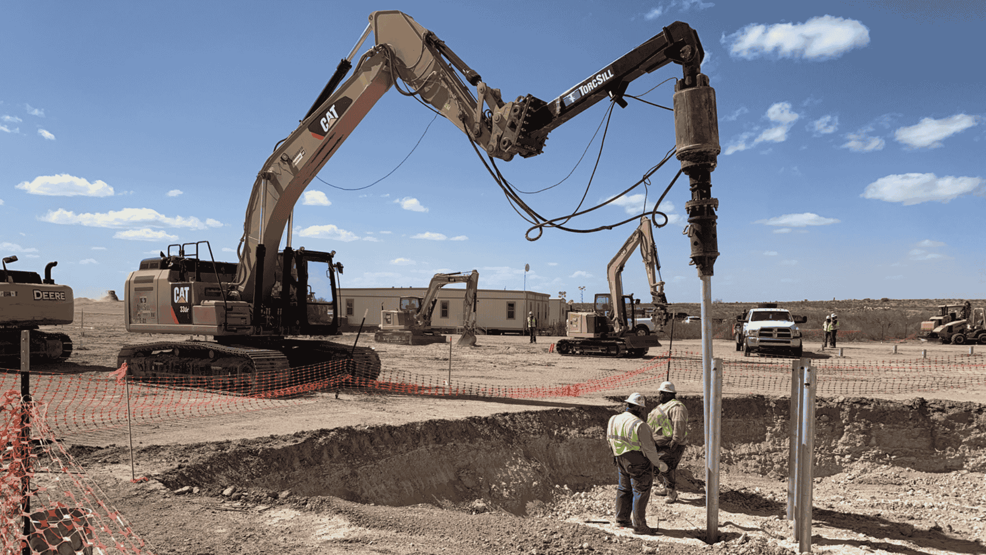
1. Torque Method
The torque method is one of the most widely used and practical approaches for estimating helical pile capacity during installation, particularly where real-time verification is required.
Relationship Between Torque and Capacity
Installation torque is directly related to the soil resistance mobilized by the helices. Empirical correlations link final installation torque to ultimate axial capacity, typically expressed as:
Ultimate Capacity = K × Installation Torque
Where K is an empirical correlation factor influenced by soil type, pile geometry, and installation conditions.
When properly calibrated, this relationship allows contractors and engineers to confirm in real time that the target design capacity has been achieved, an advantage on sites with variable stratigraphy or limited access for extensive testing.
Where Torque Correlation Becomes Less Reliable
While effective, the torque method introduces project-specific risk when subsurface conditions or loading demands fall outside well-characterized ranges. The reliability of the K-factor varies most noticeably in the following scenarios:
Sand vs. Clay Soils: In dense sands, torque typically correlates well with end-bearing resistance at the helices. In soft to medium clays, however, installation torque may reflect remolding resistance rather than long-term shear strength, leading to potential overestimation of capacity if not adjusted for soil sensitivity and consolidation behavior.
Onshore vs. Offshore or Marine Sites: Offshore and waterfront environments often involve layered soils, loose marine sediments, or high groundwater pressures. In these conditions, torque measurements may be influenced by temporary excess pore pressures or variable confinement, reducing the reliability of standard torque-to-capacity correlations without site-specific calibration or load testing.
Variable or Layered Stratigraphy: Where piles advance through alternating weak and competent layers, torque may spike locally without the helices being fully embedded in the intended bearing stratum. Relying solely on final torque in such cases can mask insufficient embedment depth.
High-Capacity Energy and Industrial Foundations: For heavily loaded energy infrastructure, uplift-critical foundations, or cyclic loading applications, small errors in torque correlation can translate into significant performance risk. These projects typically require supplemental analytical checks or proof testing to validate torque-derived capacities.
Factors Influencing Accuracy
Torque-based capacity estimates are influenced by several installation and soil-related variables:
Soil Type and Density: Cohesive and cohesionless soils mobilize resistance differently during installation.
Pile Geometry: Shaft diameter, helix diameter, and helix spacing affect both torque demand and load transfer mechanisms.
Installation Method: Rotation rate, applied crowd force, and equipment calibration directly affect measured torque.
Soil Disturbance: Excessive remolding, obstructions, or installation interruptions can skew torque readings.
For these reasons, torque-derived capacities should be treated as a verification tool—not a standalone design method. Best practice pairs torque monitoring with geotechnical analysis and, where risk or loading demands justify it, field load testing to confirm long-term performance.
2. Engineering Calculations
Analytical calculations provide the theoretical basis for helical pile design and are essential for code compliance and design documentation.
Bearing Resistance and Shaft Contribution
Axial capacity is calculated by summing:
Bearing resistance at each helix, based on soil strength and helix area
Shaft resistance, where applicable, particularly in cohesive soils
Each helix is treated as an individual bearing element embedded in soil with defined strength parameters.
Factor of Safety Application
To convert ultimate capacity into allowable capacity, engineers apply a factor of safety, typically:
2.0 to 2.5 for axial compression
Higher factors where soil uncertainty or critical loading exists
These factors ensure acceptable performance under service loads and account for variability in soil conditions and installation.
Sizing and Geometry Considerations
Engineering calculations also guide:
Required pile length to reach competent strata
Shaft diameter selection for structural capacity
Helix size and spacing to meet load demands without excessive settlement
3. Load Testing and Verification
Load testing provides direct, measured confirmation of helical pile performance and is typically recommended when project risk, loading complexity, or regulatory oversight exceeds what torque correlation and analytical design alone can reliably address.
When Load Testing Becomes Necessary
While many projects can be safely executed using torque-based verification calibrated to geotechnical data, TorcSill typically recommends proof or verification testing under the following conditions:
High-Risk or Critical Structures: Foundations supporting essential infrastructure, such as power generation facilities, substations, marine structures, or mission-critical industrial equipment, often require load testing to reduce uncertainty and demonstrate defensible performance.
Regulatory- or Owner-Driven Requirements: Transportation, energy, and public-sector projects governed by agencies such as DOTs, utilities, or port authorities frequently mandate load testing to satisfy permitting, acceptance, or third-party review criteria.
First-of-Kind or Unfamiliar Soil Conditions: Projects in highly variable, layered, or poorly characterized soils, such as soft marine sediments, highly sensitive clays, or reclaimed land, benefit from load testing to validate design assumptions and torque correlations.
Uplift- or Lateral-Controlled Designs: Where uplift resistance or lateral deflection governs foundation performance, load testing provides confidence that anchors and shafts will perform as intended under service and extreme loading conditions.
High Load Demand or Limited Redundancy: Foundations with high individual pile loads, tight settlement tolerances, or minimal redundancy often justify testing to confirm capacity and stiffness before full-scale installation proceeds.
Common Load Testing Methods
Static Axial Load Testing: Compression load tests verify downward capacity and settlement behavior under controlled loading, providing direct confirmation of serviceability and ultimate performance.
Tension (Uplift) Testing: Uplift tests confirm anchor performance for structures subject to wind, buoyancy, wave action, or overturning moments.
Lateral Load Testing: Lateral tests evaluate horizontal resistance, pile stiffness, and bending behavior, critical for marine, energy, and industrial structures.
Performance Monitoring: In select applications, long-term monitoring is used to evaluate settlement, creep, or cyclic performance over time, further reducing uncertainty for long-life assets.
By applying load testing selectively, where risk, regulation, or uncertainty justifies it, TorcSill helps project teams balance safety, cost, and schedule while delivering foundation performance that is both verifiable and code-compliant.
Helical Pile Design Considerations
Once target loads and site conditions are defined, helical pile design focuses on selecting the appropriate pile geometry and configuration to safely and efficiently meet project requirements.
Proper design balances geotechnical capacity, structural strength, constructability, and long-term performance.
Pile Diameter, Helix Size, and Configuration
Helical pile design begins with selecting:
Shaft diameter, which governs structural strength and bending resistance
Helix diameter, which directly affects axial and uplift capacity
Number and spacing of helices, which control how the load is distributed into the soil
Helices are typically spaced to prevent overlapping stress zones, ensuring each helix contributes effectively to total capacity. Larger helices or additional helices are often used in weaker soils or where uplift loads govern design.
Maximum Recommended Loads per Pile Type
Each pile configuration has practical load limits based on:
Structural capacity of the steel shaft
Weld strength between the shaft and helices
Installation torque limitations
Applicable design codes and safety factors
Exceeding recommended limits can lead to excessive deflection, buckling, or long-term performance issues. For heavy industrial or energy applications, piles are often custom-designed to accommodate higher loads while maintaining safety margins.
Group Pile Interaction and Spacing
When multiple helical piles are used to support a structure, group effects must be considered. Closely spaced piles can experience reduced efficiency due to overlapping stress zones in the soil.
Typical design considerations include:
Minimum center-to-center spacing, often expressed as a multiple of helix diameter
Load distribution through pile caps or grade beams
Differential settlement control
Proper spacing ensures predictable performance and avoids unintended reductions in capacity.
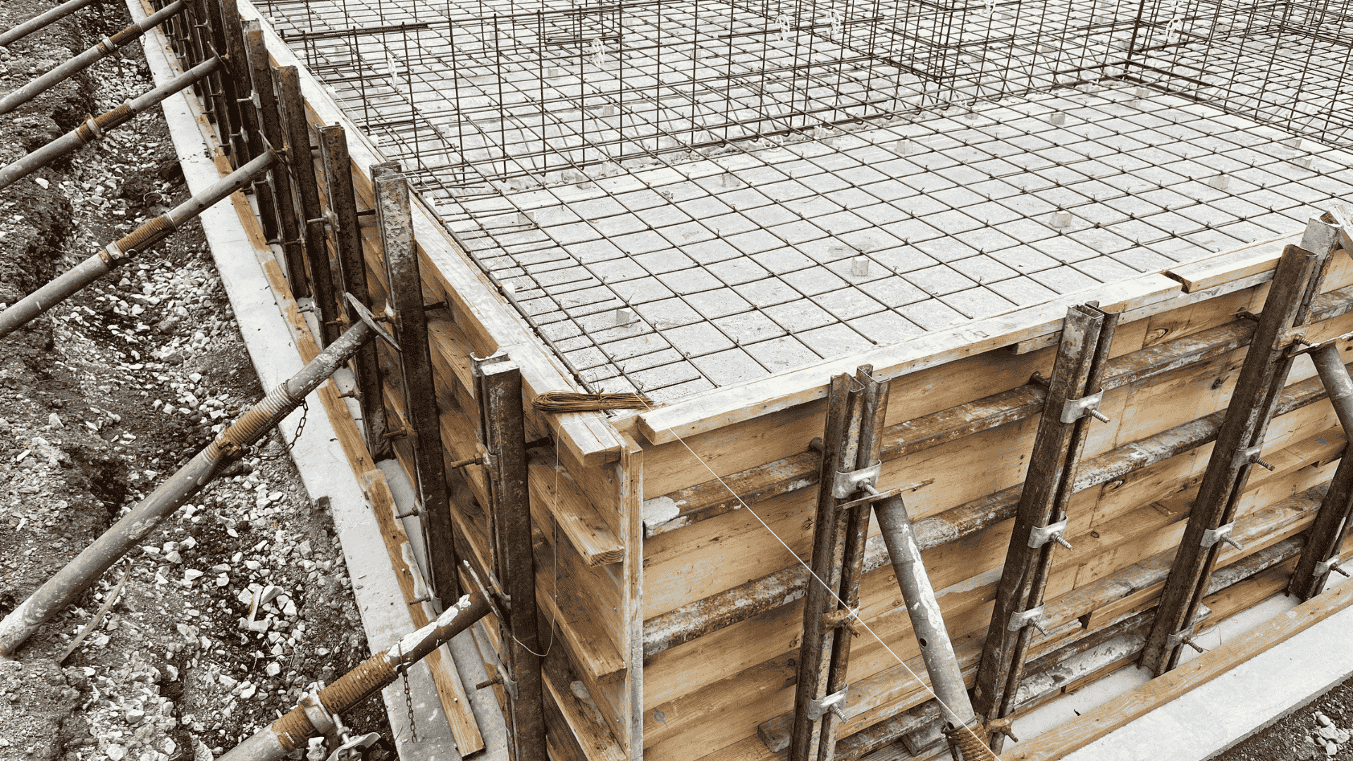
Structural Connection Design
The interface between the helical pile and the supported structure is a critical design element, governing load transfer, constructability, and construction sequencing. Common connection types include:
Steel-to-steel connections, such as brackets or pile caps, welded or bolted directly to structural steel
Concrete interfaces, where piles are embedded in or connected to cast-in-place elements
Connection design must accommodate axial, lateral, and uplift loads, as well as construction tolerances and alignment requirements.
Immediate Loading and Fast-Track Project Advantages
In energy, power, and industrial projects operating on compressed schedules, helical pile connections are often engineered for immediate loading after installation, a key differentiator from traditional cast-in-place or driven foundation systems.
This capability delivers several critical advantages:
Schedule Acceleration: Immediate load transfer eliminates concrete curing time, allowing structural steel, equipment skids, transformers, or modular units to be set the same day piles are installed. This directly shortens the critical path for substations, power generation facilities, and renewable energy projects.
Improved Construction Safety: Faster progression from foundation installation to superstructure erection reduces open excavations, temporary shoring, and extended site exposure, lowering safety risk on active energy and industrial sites.
Reduced Temporary Works and Rehandling: Engineered steel-to-steel connections minimize the need for temporary supports or staged loading, improving installation efficiency and reducing crane time and site congestion.
Predictable Load Transfer: Because helical pile capacity is verified during installation, connections can be designed with confidence to accept service loads immediately, supporting early commissioning and testing of power and energy assets.
For fast-track energy and power projects where downtime, weather exposure, and safety risk carry high cost, immediate-load structural connections allow helical pile foundations to support both accelerated construction schedules and safer execution without sacrificing performance or compliance.
Safety Factors and Code Compliance
Safety factors and code compliance play a central role in ensuring helical pile foundations perform reliably under both normal operating conditions and extreme events. In the United States, helical pile design must align with nationally recognized codes while also addressing project-specific risk and loading requirements.
Applicable Codes and Standards
Helical pile design and installation are commonly governed by a combination of the following:
International Building Code (IBC): Provides general foundation design requirements and acceptance criteria
ASCE 7: Defines minimum design loads, including wind, seismic, and snow
AASHTO: Applies to transportation and infrastructure projects
API standards: Often referenced for energy and industrial applications
Local and state building codes: May impose additional requirements or testing provisions
Compliance with these standards ensures consistency, safety, and regulatory approval across jurisdictions.
Recommended Design Safety Factors
Safety factors are applied to account for uncertainty in soil conditions, installation variability, and load assumptions. Typical practices include:
Axial compression and uplift loads: Factors of safety generally ranging from 2.0 to 2.5
Lateral loads: Evaluated using deflection-based criteria and structural checks
Group pile systems: Additional conservatism where load redistribution may occur
The selection of appropriate safety factors depends on soil variability, the quality of geotechnical data, and the criticality of the supported structure.
Serviceability and Ultimate Limit States
Designers must verify performance under both:
Serviceability limit states, controlling settlement, rotation, and deflection
Ultimate limit states, preventing structural or geotechnical failure
Helical piles are typically designed using allowable stress principles for geotechnical capacity, with structural elements checked using factored loads per applicable codes.
Common Challenges in Capacity Determination
Even with sound engineering principles and established design methods, determining accurate helical pile capacity can present challenges, particularly on complex or variable sites. Recognizing these common issues helps engineers and project teams avoid costly errors and improve foundation reliability.
Soil Variability and Limited Geotechnical Data
One of the most frequent challenges is inadequate or incomplete subsurface information. Soil conditions can change significantly across a site, and limited borings or testing may not capture weak layers or anomalies.
Consequences include:
Unexpected refusal or insufficient torque during installation
Overly conservative designs that increase cost
Localized settlement or performance variability
Supplemental investigations or real-time torque monitoring can help mitigate these risks.
Overestimating Capacity in Soft or Loose Soils
In soft clays, loose sands, or highly organic soils, apparent installation resistance may not translate into long-term capacity. Overreliance on torque data without proper calibration can result in inflated capacity estimates.
This is especially critical for uplift and long-term loading conditions where soil creep or consolidation may occur.
Ignoring Lateral Load Effects
Designs that focus solely on axial capacity may overlook lateral loads and bending demands. In energy, marine, and industrial applications, lateral forces often govern pile size and embedment depth.
Failure to account for lateral loading can lead to excessive deflection or connection overstress.
Errors in Torque-to-Capacity Correlation
Using generalized or non-project-specific torque factors can introduce significant uncertainty. Torque correlations should be based on:
Pile geometry
Soil type
Installation method
Project-specific experience or testing
Incorrect correlations can undermine the reliability of torque-based verification.
Applications Where Accurate Capacity Determination Matters
Accurate determination of helical pile capacity is especially critical in applications where foundation performance directly affects safety, operability, and long-term asset value. In these sectors, even minor capacity miscalculations can result in costly downtime, repairs, or regulatory issues.
Energy Infrastructure
Helical piles are widely used for energy-related facilities such as:
Well pads and drilling support structures
Pipe racks and pipeline supports
Renewable energy installations
These structures often experience combined axial, lateral, and uplift loads, along with cyclic forces. Precise capacity determination ensures stability under both operating and extreme environmental conditions.
Industrial Facilities and Heavy Equipment Foundations
Industrial applications frequently involve high point loads, vibration, and dynamic forces from rotating or impact equipment. Accurate pile capacity calculations help control settlement, prevent misalignment, and maintain operational reliability for critical systems.
Marine and Waterfront Structures
Marine environments introduce unique challenges, including:
Buoyancy and uplift from high groundwater
Wave and current-induced lateral loads
Variable and often weak subsurface soils
Accurate capacity assessment is essential for piers, bulkheads, mooring structures, and river crossings where failure can have severe environmental and economic consequences.
Power Generation and Substations
Electrical substations and power generation facilities require foundations that maintain precise tolerances to protect sensitive equipment. Helical piles must be designed to resist uplift, lateral forces, and fault-induced loads without excessive movement.
TorcSill: Integrated Helical Foundation Solutions
As a leading provider of engineered helical pile foundation systems, TorcSill combines multidisciplinary engineering, certified manufacturing, and nationwide construction expertise to deliver turnkey foundation solutions across energy, industrial, power, marine, and commercial sectors.
What sets TorcSill apart:
Vertically integrated services, from soil and load analysis to pile design, fabrication, installation, and field verification, ensuring seamless coordination across all project phases.
ISO 9001:2015 certified manufacturing with AWS D1.1 fabrication standards, producing high-quality, customizable helical piles and components.
Professional engineering services licensed in multiple states, offering torque profile analysis, finite element design, P.E.-stamped calculations, and onsite engineering support.
Nationwide construction services with strategically located operations and highly trained crews capable of installing helical piles under diverse site conditions.
Advanced foundation technologies, including steel-to-steel connections and specialized solutions like AnchorPipe and Onshore Platform systems for unique load and site requirements.
TorcSill’s approach eliminates the uncertainties often associated with traditional foundations by ensuring design assumptions, fabrication quality, and field execution are fully aligned. Schedule a call today to get started.
Conclusion
Determining helical pile capacity and load requirements is a multi-step engineering process that directly influences foundation performance, safety, and project efficiency. Accurate capacity determination begins with a thorough understanding of structural loads and subsurface conditions and continues through careful design, installation, and field verification.
Need Engineered Helical Pile Solutions with Verified Load Capacity?
When foundation performance is critical, assumptions aren’t enough. TorcSill delivers engineered, turnkey helical pile solutions designed, installed, and verified to meet exact load requirements across the most demanding soil and site conditions in the U.S.
Whether you’re supporting energy infrastructure, industrial equipment, marine structures, or temporary platforms, TorcSill helps ensure your foundation capacity is proven, defensible, and built to perform from day one.
Talk to TorcSill’s engineering team to evaluate your load requirements and design a helical pile solution that reduces risk and accelerates construction.
FAQs:
1. How early in a project should helical pile capacity be evaluated?
Helical pile capacity should be evaluated during early site feasibility or conceptual design to influence layout, access planning, and foundation selection before structural design is finalized.
2. Can helical pile capacity be adjusted during installation if site conditions change?
Yes. Helical piles allow field adjustments such as extending pile depth or modifying configuration to reach the required capacity without redesigning the entire foundation system.
3. Are helical piles suitable for projects with tight construction schedules?
Helical piles are well-suited for fast-track projects because they require no curing time and can be loaded immediately after installation, reducing critical path delays.
4. How does corrosion potential affect long-term pile capacity?
Corrosive environments can reduce the effective steel cross-section over time. Protective coatings, sacrificial thickness, or material selection are used to maintain long-term structural performance.
5. Do helical piles perform well under cyclic or fatigue loading?
When properly designed, helical piles perform reliably under cyclic loads from wind, waves, or equipment, but fatigue considerations must be addressed during engineering.